
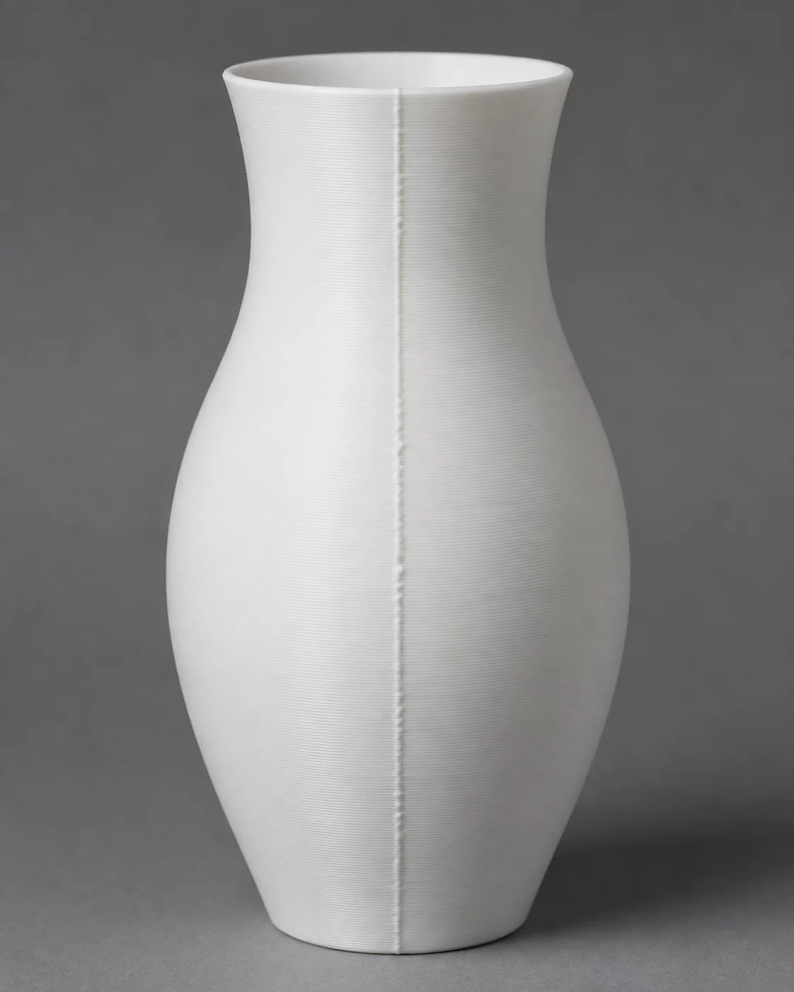
Every continuous outer perimeter in fused filament fabrication must initiate and conclude at a discrete spatial waypoint. When internal nozzle chamber pressure fluctuates during rapid axis acceleration or deceleration around these transition coordinates, a prominent vertical scar or series of localized pits forms along the exterior surface. In cylindrical vessels and continuous curved housings, this artifact presents as an unmistakable vertical zipper line known as the Z-seam.
Root Cause Topology & Mechanical Origins
The primary root cause of seam prominence resides in transient melt pressure delays occurring immediately between retraction and un-retraction cycles. As the toolhead decelerates to terminate a closed loop, residual nozzle pressure causes molten plastic to ooze slightly before the retract move takes effect, leaving a raised micro-blob. Conversely, when commencing the subsequent layer, brief lag in pressure re-establishment often generates small depressions or under-extrusion voids directly at the seam origin.
Advanced slicing engines mitigate these visual disruptions through targeted alignment algorithms including Aligned, Back, Nearest, and Random distribution modes. Slicing with random seam placement on a smooth cylinder distributes distinct extrusion blips across the whole circumference, multiplying cosmetic flaws. Applying calibrated pressure advance, coasting parameters, and scarf-joint wall intersections ensures the toolpath entry and exit blend seamlessly into the adjacent perimeter wall.
Systematic Calibration & Recovery Directives
- Calibrate Linear Advance / Pressure Advance (PA) to synchronize nozzle chamber extrusion pressure with dynamic toolhead acceleration.
- Set seam placement mode to 'Aligned' or 'Back' within slicer profiles, or align seam coordinates directly inside concave corner features.
- Enable 'Wipe While Retracting' (0.4 to 0.8 mm) and tune seam gap percentage down to 10–15% to stop outward extrusion bulging at perimeter termination.
By harmonizing melt flow dynamics with deliberate slicer seam placement, the tactile seam height can be constrained below 0.03 mm, safeguarding cosmetic quality and critical slip-fit tolerances across high-precision mechanical assemblies.
Forensic Discussion & Logs
Tuning the outer wall wipe distance to 0.60 mm combined with a 12% seam gap reduction eliminated the outer start/stop ridge on cylindrical test specimens. Optical coordinate scanning confirmed a reduction in tactile deviation from 0.11 mm down to 0.02 mm.
Append Telemetry Observation