
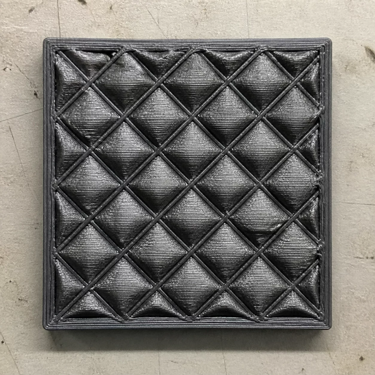
Pillowing manifests as an irregular array of raised bumps, tiny craters, or ruptured pinholes across the uppermost horizontal surfaces of a printed component. Under microscopic inspection, these surface protrusions mirror the layout of the internal infill cells directly beneath them. When the molten filament is laid down to bridge across sparse internal gaps, lack of localized structural support and excessive radiant heat cause the extruded strands to droop, deform, and trap expanding air pockets inside each cavity.
Root Cause Topology & Mechanical Origins
The primary thermodynamic cause of pillowing is inadequate cooling combined with insufficient solid top layer thickness over low-density infill geometries. As the hot nozzle passes over the open cells of the infill matrix, radiant thermal energy heats the trapped air inside each pocket. This heated air expands upward against the unsupported bridge layer while it is still in a viscous, glass-transition state. If the part cooling blower fails to solidify the plastic skin instantly, the expanding air pushes the soft plastic upward into miniature domes or bursts through the skin entirely.
Secondary contributors include infill pattern selection and high extrusion temperatures. Sparse linear or grid patterns create wide spans that demand aggressive bridging dynamics. When slicing parameters specify only two or three top solid layers at standard layer heights, subsequent extrusions simply mirror the sagging profile of the initial bridge rather than ironing it flat. Achieving a mirror-flat top skin requires balancing airflow velocity, bridging density, and adequate sacrificial capping layers.
Systematic Calibration & Recovery Directives
- Increase the top solid layer count to a minimum of 5 to 6 layers (ensuring at least 0.8mm to 1.0mm total solid top thickness).
- Elevate auxiliary and part cooling fan speeds to 100% during bridging and top surface extrusion sequences to instantly freeze bridging strands.
- Transition from sparse rectilinear or grid infill patterns to continuous gyroid or adaptive cubic geometries at no less than 15% density.
Applying these systematic thermal and slicing adjustments eliminates trapped heat pockets, stabilizes the bridging interface, and guarantees uniformly dense, flat top surfaces even on high-speed industrial workflows.
Forensic Discussion & Logs
No comments yet. Be the first to leave a comment.
Append Telemetry Observation