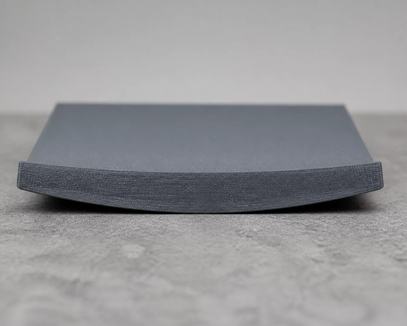
Base warping represents one of the most disruptive dimensional failure modes in extrusion-based 3D printing. It exhibits as the upward curling and detachment of bottom corners or peripheral perimeters away from the build plate. This detachment distorts the geometric flatness of mounting planes, alters part height tolerances, and frequently induces subsequent nozzle collisions during multi-hour fabrication runs.
Root Cause Topology & Mechanical Origins
The thermodynamic catalyst behind corner lifting is differential volumetric shrinkage. As molten thermoplastic cools from its extrusion temperature toward ambient conditions, each deposited line undergoes thermal contraction. When higher layers contract faster than the lower layers clamped against the heated bed, internal tensile stress accumulates across the model. As this cumulative shear force exceeds the adhesion capacity between the build surface and the initial layer, the corners detach and pull upward.
Secondary factors drastically worsen base warping. Microscopic grease and oil deposits on PEI sheets prevent full molecular wetting of the initial extruded trace. Furthermore, aggressive auxiliary part cooling fans directed toward the lower perimeter create sudden localized temperature drops, triggering rapid shrinkage before successive layers establish solid interfacial bonding.
Systematic Calibration & Recovery Directives
- Degrease the build plate with warm water and surfactant dish soap, followed by a final lint-free 99% IPA wipe to restore virgin surface energy.
- Increase first-layer extrusion line width to 125–140% and lower initial print velocity to 20 mm/s to maximize the contact footprint.
- Disable auxiliary part cooling fans for the first 4 to 6 layers and generate an 8mm outer brim with zero model gap on high-risk corner vertices.
Implementing targeted thermal envelope control alongside strict first-layer bed hygiene creates an enduring mechanical anchor, ensuring sharp geometric corners remain perfectly planar across full operational print cycles.
Forensic Discussion & Logs
Our thermal imaging audit showed a 14°C temperature drop along the front bed perimeter caused by draft infiltration. Elevating the heated bed setpoint by 6°C and establishing a 5-layer delayed fan curve eliminated bottom corner curling completely.
Append Telemetry Observation