
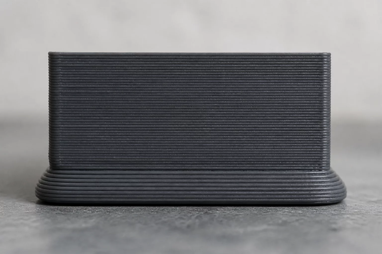
Elephant foot manifests as an outward flaring or flared collar across the bottom layers of a printed part directly above the build plate. It compromises strict dimensional tolerances, prevents mating parts from interlocking cleanly, and ruins bottom bevels. The issue typically originates right at the boundary between mechanical bed adhesion requirements and viscoelastic polymer flow dynamics during the initial phase of fabrication.
Root Cause Topology & Mechanical Origins
When the printer deposits the earliest foundation layers, the downward pressure of the nozzle combines with high build plate thermal energy to prevent rapid solidification. Successive layers add downward weight while the heated platform keeps the lowermost plastic in a rubbery, malleable state. Consequently, the molten extrusion gets squeezed outwards past the nominal perimeter path before cooling stabilizes the cross-section.
Correcting elephant foot requires calibrating both slicer-level geometry offsets and hardware baseline leveling. Slicers feature an initial layer horizontal expansion setting (or elephant foot compensation) that retracts the inner and outer perimeters of the first few layers inward by a calibrated offset, yielding uniform vertical walls once cooling occurs.
Systematic Calibration & Recovery Directives
- Apply a negative Initial Layer Horizontal Expansion (Elephant Foot Compensation) value of -0.15mm to -0.25mm in your slicing profile.
- Lower build plate temperature by 5°C to 10°C after the initial layer to keep the foundation solid and prevent gravitational thermal sag.
- Fine-tune Z-offset and first-layer flow rate to eliminate excessive mechanical nozzle squish while maintaining uniform bed contact.
Regular audit of bottom-layer dimensional calibration ensures tight interlocking tolerances across assemblies. Combining an accurate first-layer squish with appropriate slicer compensation eliminates flared edges and preserves crisp chamfers.
Forensic Discussion & Logs
Append Telemetry Observation